
Design for vibration
A question I am often asked is how smooth is your grinder. The simple answer is that on its own it is very smooth. But the overall answer is a bit more complex. To understand the problem fully we need to take a look at the basics of design for vibrations.
A basic vibratory system can be represented as:
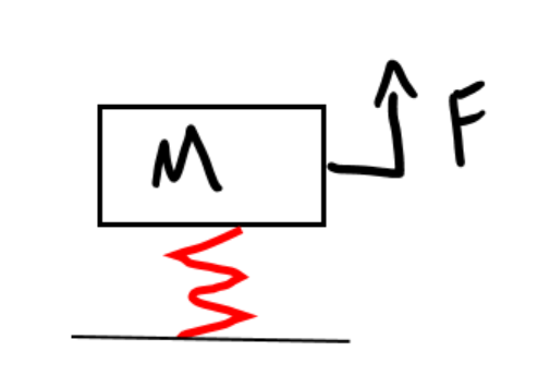
Where we have a mass (M – this is the grinder), a forcing function (F – this is the motor and drive wheel), and a spring attached to the ground (this is your support structure). One practical example of this is a flagpole. You have some mass (M) on a structure with some spring constant value (k) and a force function (F) applied by wind. If you increase the mass at the top of the pole, the natural frequency of the pole will decrease making it more susceptible to vibrations by the forcing function (wind). The natural frequency (w) of any system can be found by w=sqrt(k/m).
In the case of a grinder or other piece of equipment, the system is essentially the same just a few more variables we have to consider. First is the center of gravity of the system. Second is the location of where the force is applied.
Let us look at a simplified grinder system of the grinder without any support structure. The motor and drive wheel are spinning at some RPM. The slight variations, due to manufacturing, will cause a force to act on the grinder about the center of gravity. This forcing function will grow based on how well the motor and the drive wheel are balanced. If you have a good motor and drive wheel the force should be very small. As the motor spins this small imbalance will impart a sinusoidal (alternating) force about the center of gravity of the grinder. The distance between the force and center of gravity will determine the amplitude of vibration. There are some small things you can do in your design to help dampen the perceived vibrations. One is to use a stiff lightweight material to dampen the vibrations thru it. Think of this material as a mini natural frequency calculation within the machine. If the natural frequency is high thru the material then it will be harder to transmit vibrations.
Now let us consider the grinder and its support structure. This example the same as the flagpole example earlier just slightly different. The grinder becomes the mass at the top of the flagpole. The support structure is your spring. The forcing function is the same as the simplified grinder system. As the k value (stiffness) of the support structure decreases so will the natural frequency. As the natural frequency of the support structure gets closer to the running frequency of the motor the more the system will vibrate with the amplitude applied by the forcing function. With a VFD the frequency of the motor can be varied from 0-58 Hz.
This is where design for vibrations can get interesting. Let say your structure had a natural frequency of 25 Hz. The system would vibrate the worst once the motor reaches 25 Hz but might be smooth at 0 Hz and 50 Hz. You can also get into more complex modes of natural frequency like; modes for bending in the x direction, bending in the y direction, and twisting. Those modes are usually out of the range of the system design unless the machine was designed poorly with a weak structure.
In conclusion, the Black Fox ONE uses high quality motors and drive wheels to mitigate the vibration amplitude, a stiff ½” drive plate, spacers that are plastic infused with carbon fiber to dampen vibrations, and good design practices for vibration mitigation. If the support structure is not built well then vibrations thru the complete system are still possible. If you are experiencing vibrations, I recommend increasing the stiffness of your support structure to eliminate unwanted vibrations.